The 1951 expedition of the University Museum to British Honduras brought out a substantial tonnage of Maya stelae and altars. With Seymour A. Nuddle, a fellow graduate student in the Department of Anthropology, I went along to help, officially as assistant archaeologist. This is the story of the practical problems in getting the material ready for shipment, at the site which is called Caracol, and in restoring the Museum’s share of the monuments.
THE TROPICAL RAIN FOREST
This was not my first trip in Maya country, but it was the first time I had gotten so far off the beaten path. Darkness, true to the tropics, was falling with the heavy suddenness of a coarse woolen cloak when Sy Nuddle and I wearily sang our way into Caracol. In truth, it was Some Enchanted Evening! Led by one of the Maya boys, we were at the tag end of a fourteen-mile hike over rough trails, slimy and sticky and inches deep with mud from the last drenchings of the rainy season. But even physical fatigue evaporated in the heady exhilaration of our first glimpse of the shadowy jungle-covered ruins looming ghostily all about us. Our temporary camp, where Dr. Satterthwaite had supper and steaming coffee waiting, was, in fact, nestled in a shallow canyon fashioned by two such half-alive buildings. The weeks made tired with preparation and hopeful imagination were at last over.
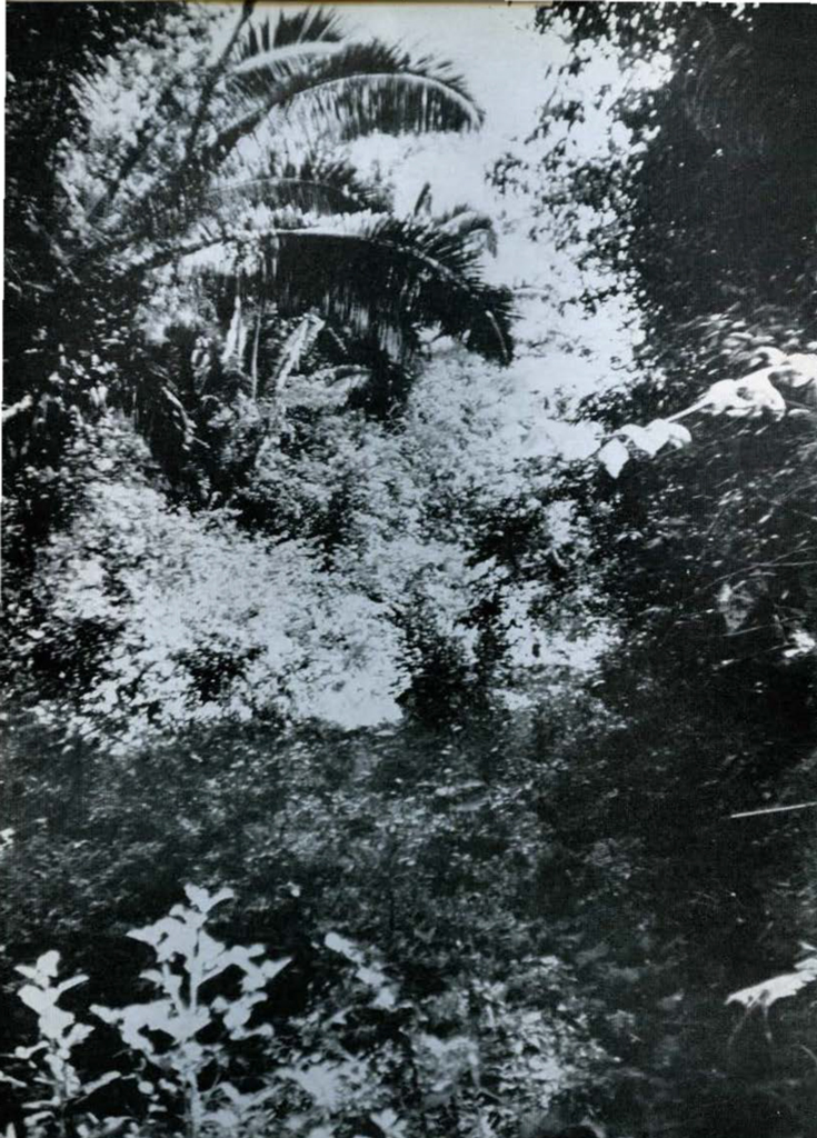
The “bush” is the popular name for the tropical rain forest (Fig. 43). Around Caracol it consists of giant mahoganies, cottonwoods and sapodillas (the chicle chewing-gum tree), rather thickly interspersed with breadnuts, pimientos, and such lesser varieties. This topmost level, soaring upwards over a hundred feet, successfully screens the sun’s rays, except those golden few which somehow manage to elude that swaying green mass. Straight-boled cohune palms, contested every inch by other palms, smaller hardwoods, giant ferns and a tangle of vines, dominate the limited light trapped by the overhead leviathans. But it is neither dark nor fetid. There is always a whisper of air-if one would stop to discover it-which moves the palm fronds in the slow-motion majesty of an underwater ballet. The constant rippling of the tree tops alternately obscures one sunbeam only to allow another momentarily to burst forth.
As movements are a constant feature of the bush, so are green hues. Every palm is a shimmering iridescent entity as each escaping light beam first highlights and then obscures it. The new shoots are yellow with youth, while the larger fronds are deep green with age. An emerald moss minimizes the porcelain white trunks of giant fig trees among the more sober rudely browns of mahogany and the endless miles of ground creepers and overhead vines.
In and out of this verdant backdrop flit tiny birds of garish yellow, and butterflies with unbelievably pure blue wings. Overhead, colonies of squawking yellow-green parrots come and go. Twice the brilliantly plumed macaw condescended to visit. The bush harbors such a complexity of strange life as to make it a veritable heaven for the zoologist and the botanist.
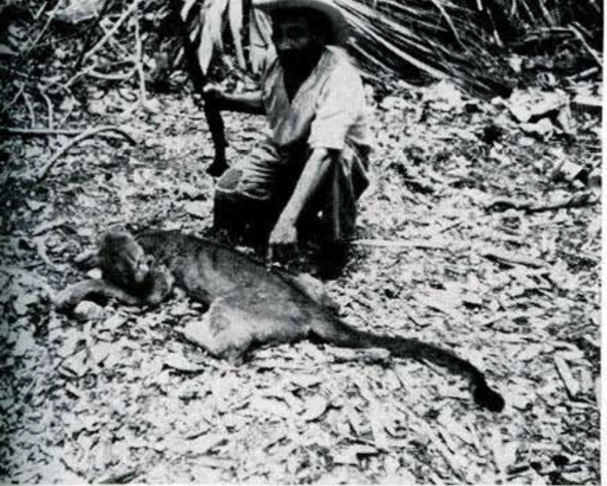
Occasionally we augmented our canned diet with wild peccary or a coal-black pheasant-like wildfowl. The shy tapir and stealthy puma (Fig. 46) visited at night, and, of course, both spider and howler monkeys were always somewhere about. Scorpions were hardly a problem, and I would rather take my chances with the few poisonous snakes than I would with some of my friends’ auto driving. All in all, the bush is a vibrant place of changing moods. I like it.
CAMP
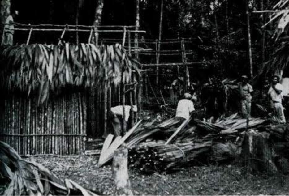
Still virtually untouched in 1951, Caracol lay under this beautiful but entangling mantle. How large was our site? How many more spectacular monuments existed? Where would be the best spot for our permanent camp? A host of questions arose, but the latter was the most quickly solved. Dr. Satterthwaite selected a small level stretch just west of a large quadrangle of buildings. The boys fell to with a will on our guano-palm thatched huts.
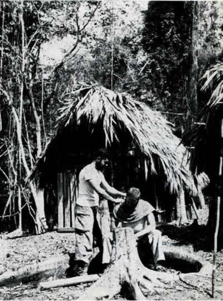
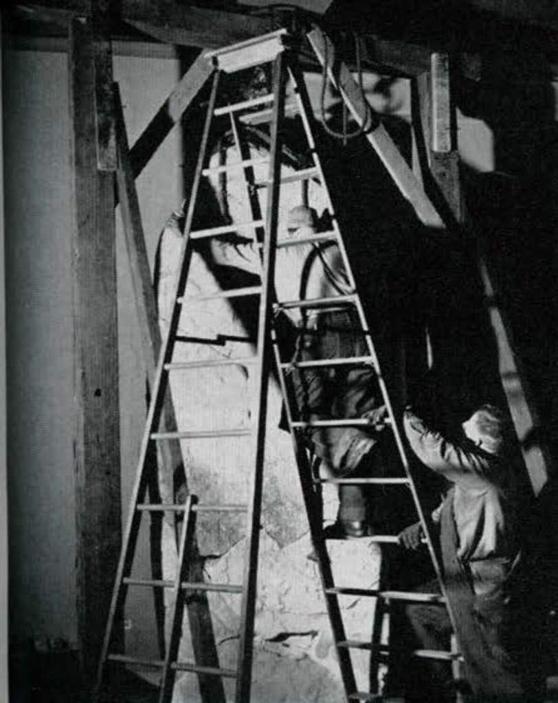
My house, for example, enclosed some 6 by 10 feet. Six stout forked posts carried the gabled roof, a lattice-like frame which securely bedded the thatching. The side walls, to the eaves, were made of long trimmed sticks that provided natural beauty while still allowing for a goodly supply of authentic air-conditioning. Nails were disdained, and the boys securely lashed this whole framework together with vines (Fig. 44).
These huts were very firm, for in 1953 they were used again, only the thatch needing partial replacement. Inside I slung my hammock diagonally from two extreme comers, put up benches and a desk of “bamboo,” and devoted one comer to a small platform for bucket bathing.
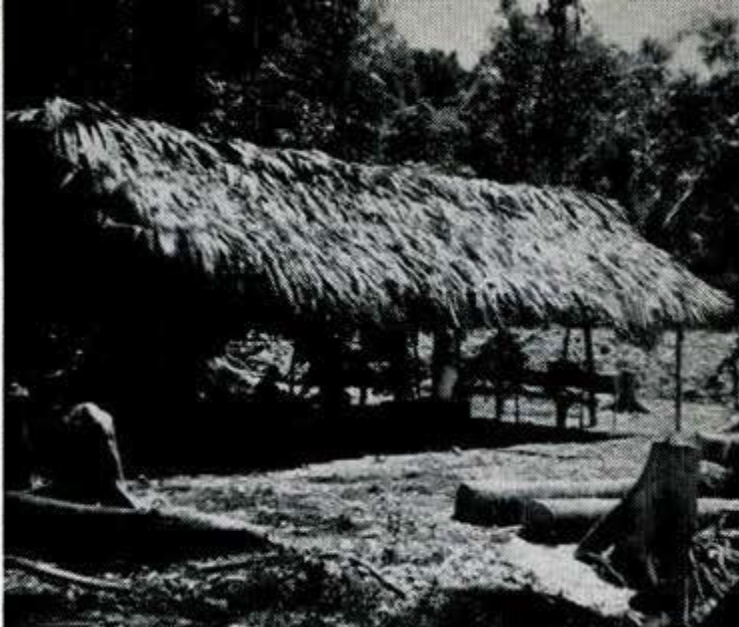
Soon the main house, warehouse, kitchen and our individual quarters were readied. The guest house even had a door (Fig. 47). To the west was an unimpaired view of the magnificent tropical sunsets. All about us Caracol waited.
SEARCHING FOR MOUNDS AND MONUMENTS
Cautiously, then confidently, trails spread out from camp into the choked plazas, over the sprouting ruins of temples and sometimes into the dead end of the bush itself. Shortly, these trails, or picados, disclosed that the heart of the site was located on an artificially flattened hilltop. Our camp proved to be at the western extreme of this. In some parts this primary area was extended by terracing. A scale map of the perimeter of the hill was paced off, and a sketch map made of the buildings within.
Then, in turn, each ruin and plaza was carefully scrutinized. For the building mounds this was a simple matter. However, the larger plazas, often with clusters of thorny vines, presented a far more difficult problem. Hard, steady machete work was the answer. A straight, clear path was cut along one side of the plaza. Then, at right angles to this and about every ten meters, fresh picados were hacked out across to the opposite side of the plaza. The use of a Brunton compass prevented possible drift from this grid. At first, to my eager, untrained eye, every fallen log became a stela and every pebble an altar. But that soon passed, though several of the heartbreaking false alarms required excavation to prove their deception.
Twelve more monuments were found to go with the twenty-five located by 1950. Yet, still later, in 1953, the whole bottom half of a stela, in a superb state of preservation, was discovered not ten feet from our main supply “road” out to the logging trails.
MISCELLANEOUS CHORES
Our job was to take out these stelae and altars before the jungle exacted an even greater destructive toll. However, this was not all. While there, Mr. Nuddle handled the mapping chores; I prepared the monuments for shipment. Dr. Satterthwaite not only oversaw both these operations but also undertook such necessary minutiae as specific spot digging, organizing the catalogue system, drawing and deciphering the calendrical evidence, and laboring with the dirty job of corresponding secretary. Actually, these rigid limits were impractical to maintain as such, so that each assisted the others whenever possible. All three of us became photographers, though not in a class with Bachrach, but rather because the camera has become as essential to the archaeologist as people and soapboxes to politicians. With the aid of a gasoline engine for our photoflood lights, we were able to procure at night many excellent shots of the monuments under controlled lighting conditions. The area about each monument had to be carefully excavated with the result that three caches, miscellaneous stone, shell, bone and jade artifacts, and a fair quantity of sherds are now available for study in the Museum’s storerooms. But while such things are essential for a complete archaeological record, the monuments remained our primary point of focus.
MOVING HEAVY STONES WITHOUT DAMAGE
For the rigger, the stelae and altars of Caracol presented a wide diversity of problems. These depended not only on bulk, shape and weight, but on the carved decoration and the interrelation of these factors. Only four of the monuments we had to deal with, Stela 1, Altars 1 and 7, and Stone 28, were unbroken. The remainder had been fractured by falling trees, the growth action of ground creepers and, mysteriously enough, possibly by man himself.
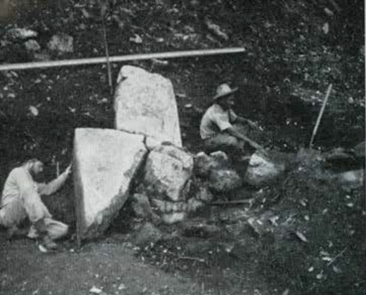
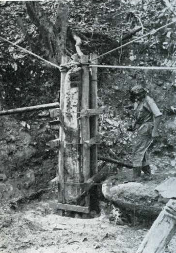
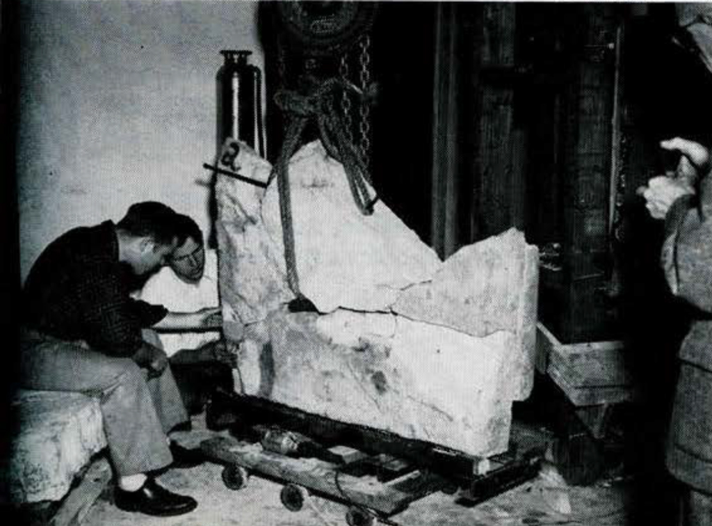
Stela 6, now in the Middle American Hall, had collapsed like a house of cards into some six chief fragments, and many small ones. They ranged in size from that of a postage stamp to a section weighing about a ton. To complicate matters, this stone had carried very fine relief on all four sides, so that by moving any one fragment there arose a serious danger of damage not only to that piece but also to its neighbor. On the other hand, Stela 1 was carved on one face only, was unbroken and still standing, so the easiest and most efficient solution was to crate it where it stood. Roping before digging out the base prevented it from toppling over (Fig. 50). Stela 5 had a plain back, and most of its sides were so eroded as to be plain for our purposes, but it involved difficulties similar to those at Stela 6 because of the positions of its fragments (Fig. 56).
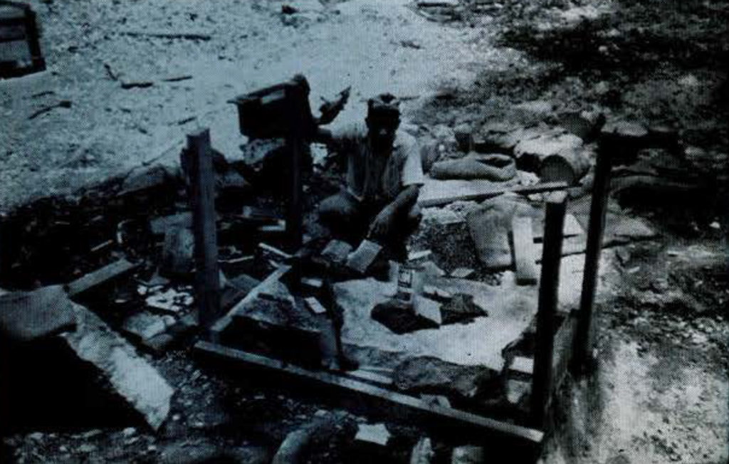
The altars, naturally, entailed no such positional problems after breakage; fractured or not, there was little danger to the relief in moving them. But, at Caracol, caches of religious offerings were known to have been secreted under some of the altars. Therefore, when removing fragments, it behooved us not to burrow haphazardly under them. Both unbroken altars were packaged in situ like Stela 1. In essence. this involved raising-jacking up-the altar onto “legs” of wooden blocks (Fig. 52). This meant, of course, that the area under the stone remained undisturbed, and, after crating, the altar could safely be moved off on “rails” (Fig. 53).
Possibly because it was both intact and in its original position. Altar 7 was chosen for a most unusual ceremony. One of our workmen offered a short prayer, including both the ancient copal incense and the Maya tongue. This appeal for the cessation of the rains and protection from danger was shot through with both Christian and Maya symbolism-indeed a rare insight into the curious amalgamation of the old and the new achieved by the reasonably acculturated Maya of this area.

The pattern of work concerning each monument was basically the same. After the precise location of the fragments had been mapped, plans and sections drawn to scale, the fragments numbered, the preliminary photographic record begun and the immediate basic excavations completed, then my knotty problem really began.
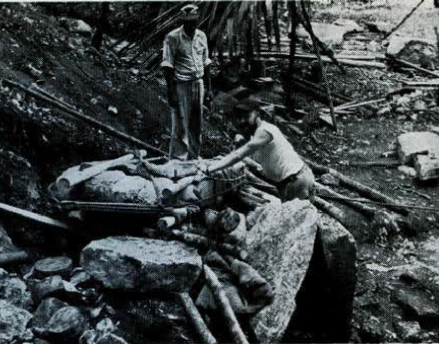
The first rigging task was to move the broken fragments to an adjacent area not only suitable for ease of photography of sculpture, but also to facilitate future packing (Fig. 58). Some of the pieces could be easily handled by Eduardo Cocom, my chief lieutenant from among the Maya boys, and myself. Sometimes it was necessary to adapt a rope sling to the stone, insert a stout pole under the loops and rely upon the sturdy backs of two or three more workmen. In all cases where roping was utilized, special pads were made to protect the friable edges and carved surfaces (Fig. 49). For these, “Ozite,” a fuzzy dark brown felt, similar to that which is placed under rugs, was cut into strips and sewn into sections cut from burlap bags. These provided soft, sturdy and pliable pads for the rope to bed on. This is typical of the necessary on-the-spot ingenuity, for the chief purpose of the Ozite, brought from home, was as a protective cover for the sculpture during the long voyage back.
In 1953 similar pads were made of sawdust, packed in burlap and quilted. Efficiency-wise, the Ozite pads were the more successful, for the sawdust had a tendency to lump and swell after being rained upon.
The majority of the fragments were dragged to their more convenient locations by a “Yale” chain hoist of l 1/2-ton capacity. The machine could be carried by two men when slung from a strong carrying pole. For dragging, the fragment, with a rope sling and pads about it and resting on a temporary wooden sledge-like platform, was hooked to the previously anchored hoist (Fig. 57). Long poles, with bark removed, were laid parallel on the ground, often with wooden stakes driven in beside them to prevent undue skew. The “rails” were greased. Then the fragments slid quite unconcernedly (Fig. 53).
An improvement was effected in 1953 by the substitution of a “Lug-All” for the chain hoists. While having the same 1 1/2-ton lifting capacity, this light machine can be carried in one hand. It is a wire rope winch operated by a lever and ratchet. This increased mobility took much of the labor from the rigging process, but we did not have it in 1951, when most of the work was done.
Well nigh every stela had its own set of specific problems and difficulties. The collapse of Stela 5, for example, had left one section resting directly on top of another (Fig. 56). Here the jack was used, in conjunction with braces, so that the stone eventually sat on four wooden “legs,” and the rail technique could then be utilized.
The jack was always a problem, for the weight of the fragments would drive it into the soft earth rather than lift the stone. Dr. Satterthwaite ingeniously solved this by having the trunk of a very light but durable tree sawed into sections, some cuts being at an angle. We were thus provided with solid round bases of varying thicknesses and “tilts,” so that the head of the jack always rested firmly at a right angle against the stone.
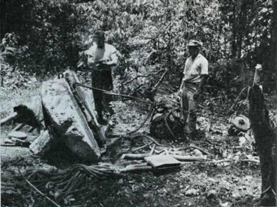
Occasionally it was necessary to rig the block and tackle as a counter-poise. This was done, with Stelae 3, 5, and 6, primarily to prevent a side-wise movement into an adjacent exposed fragment. Once, because of the considerable weight of Stela 3, a second chain hoist as an added safety factor was used for this purpose. In some instances, notably Altars l and 7, earthen rail beds were built up in order to cross either shallow depressions or outcroppings of rubble (Fig. 54).
The weight of the fragments was of small concern, except as a constant source of irritation in case of slipping or possible breaking of the rope. Concern for the safety of the men naturally resulted in as much care for them as for the monuments. New equipment, particularly rope, is vital. Also, in cases of even slightly doubtful stress, the rope was doubled. Still, in their eagerness, the boys would sometimes work in a potentially dangerous spot, or put their hands under a ton of temporarily braced limestone. Shortly, however, they understood that such risks were to be undertaken only by me.

Happily, the only disaster occurred when I hammered my finger nail instead of the iron one. I expressed profused discomfort in English, Spanish and Maya (the latter mostly for the benefit of the boys), and all was soon forgotten.
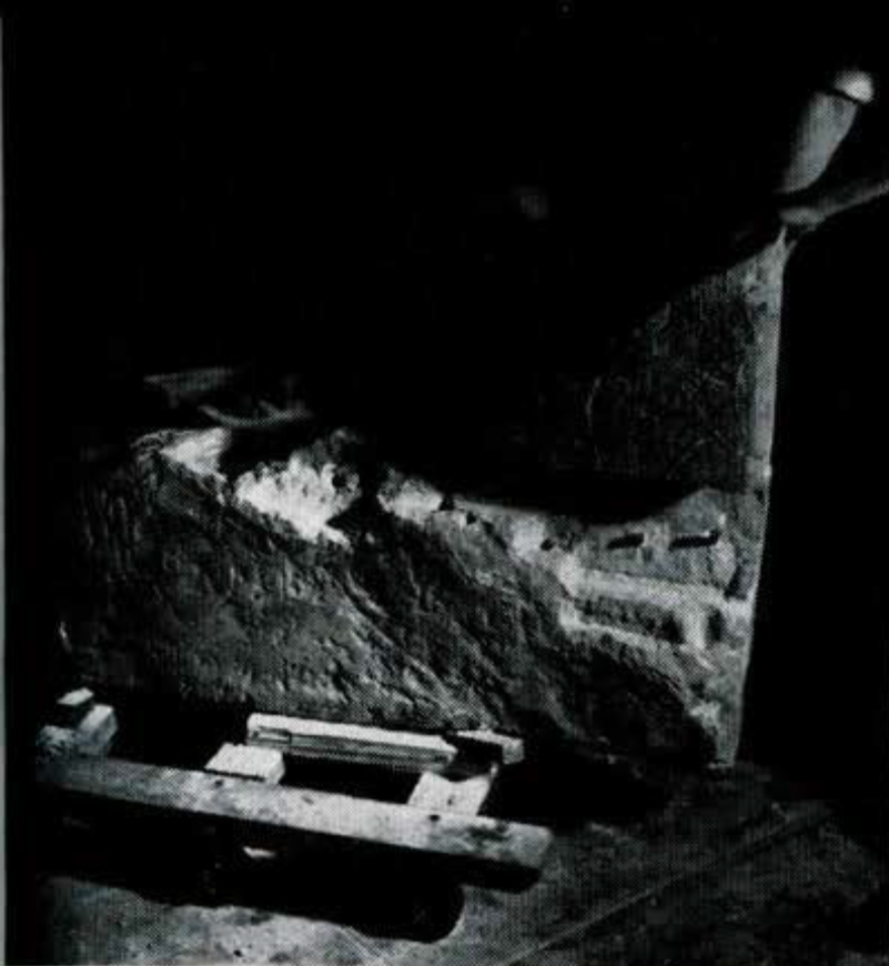
Night photography is the prime method by which to obtain superior results with relief sculpture. The key, of course, is controlled light. Our portable gasoline engine supplied the power for the photofloods, and an extra-long cable allowed for complete freedom of movement. The position of the light-or lights, if backlighting was desired-was dictated by that angle found best for the delineation of the relief by shadow and highlight.
Obviously many “straight-on” views were needed, without foreshortening. To get them, the stones were set on their narrow edges and braced from behind (Fig. 49). Their handling in this position was surprisingly facile. Thus either the fragment itself, or the camera, could be quickly adjusted so that the lens position was at right angles to the sculpture.
BOXING AND CRATING
This position was also most advantageous for future boxing. With a complete set of night photographs, I turned from rigging to the actual job of crating. First, outline scale drawings were made of each fragment. These served a twofold purpose. We could estimate with fair accuracy the cubic content, hence the tonnage, of each fragment, and the crates could be designed and the necessary lumber cut to specification.
The packages were of two types. For the smaller pieces, i.e., those up to 200 or 300 lbs., the most efficient method was to box them. Such boxes were usually composed of two floors, the top level for a second layer of stone being constructed only after the fragments had been placed on the bottom level (Figs. 51 and 59). In all cases the individual fragments were so braced that the pieces absolutely could not move, no matter which side of the box was turned upwards. Unpacking at the Museum has revealed no damage-not even flaking or scratching on any of the stones.
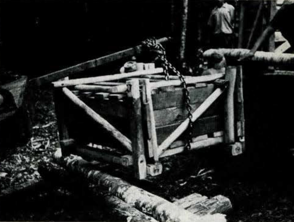
The larger stones were put into “pressure crates.” These consisted of two wooden platforms of similar construction. Each was placed against a broad face of the stone and bolted together with half-inch threaded iron rods, brought for the purpose. Naturally, with the fragments already on edge, it was no trick to dig shallow trenches on each long side, wedge the two sections into the proper position and screw down the nuts. Thus, with these sections drawn tight, the stone rested somewhat like an oyster within its external skeleton (Figs. 52 and 63) . All the wood had previously been measured, cut and drilled at camp. The scale drawings made it so that hardly a piece of wood had to be recut. Essentially, then, both the boxes and the pressure crates were prefabricated.
The history of our lumber supply is another story indeed. A sufficient supply of mill-cut lumber could not be delivered so far from real roads, though we had been counting on it. It was decided, therefore, to manufacture much of our own. “Malario,” an extremely tough and heavy wood, was found to be admirably suitable. Trees of four-inch diameter were earmarked for struts and crossbraces on both types of packages. Larger ones, up to nine-inch diameter, formed the basic foundations of the pressure crates. A tough, lighter wood was easily convertible into planks in order to stretch our meager “store-bought” supply. As the scale drawings gave us both the size and the estimated weight of each fragment, particular trees were designated for specific stones on the basis of these figures.
After the trees were felled, trimmed and sawed to proper length, and the logs dragged to camp by the jeep, two of the boys were set to shaping them. First, parallel incisions, some 20 inches apart, were sawed crosswise down the length of each side of the bole to the proper depth as required by the eventual thickness of the beam. Then, with machetes, the areas between these cuts were hacked out. The result was two remarkably smooth surfaces, opposite each other, with the original diameter of the tree still extant between them. To assist with this and other carpentry, Dr. Satterthwaite imported Gumersindo de Requeña. The addition of this experienced hand proved to be an immeasurable boon.
While the hardness of the wood gave a rigid surface for the faces of the stones, softened with Ozite, of course, it also brought forth difficulties. Even now, after seasoning, it is impossible to drive a six-inch nail into this wood, so that every rod and large nail hole had to be drilled. The large holes were bored at camp, and the small ones, for nails, during the actual construction in the field. The total operation of fabricating these packages is simplicity itself in theory, but in actuality consumed mountains of time. To help lighten this load, Eduardo Cocom, my chief Maya helper, and I often staged informal “cigarette derbies” and “candy races.” He invariably finished his job first, which added no little to his morale, our friendship, and the speed of the whole process.
Packaging completed, my task as field rigger finally terminated upon delivery of the crates and boxes to the pick-up locations. This was simple enough through the use of the chain hoist and greased rails. By this time we could smell the hay in the barn, and it was real fun, contrary to orders, to ride on Altar 7, a one-ton beauty, down the steep slope of a large temple mound. Eduardo checked against headlong flight with block and tackle, but the giddy slides and jarring ricochets were like a mild case of convulsions.
TRANSPORTATION
The transportation of the finished crates to Belize was admirably handled by a mahogany contractor, Mr. L. M. Sylvestre, whose camp “Guacamayo” was our jumping-off point. His operation was expediency itself. A “road,” merely a cleared swath, had previously been cut some l l/2 miles through the bush to the nearest lumber route to facilitate the handling of such necessary supplies as food, water, mail and laundry. His large logging trucks used this to reach the site, and, once there, several side trails were run into convenient pick-up locations.
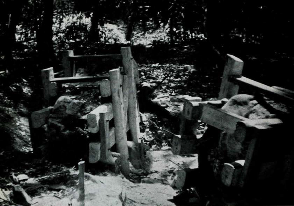
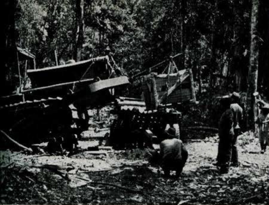
At the pick-up spots all the boxes were supported off the ground on some sort of wooden platform. Mr. Sylvestre’s crew removed the blade from the bulldozer, inserted a truck axle as a boom, and wrapped a stout chain about this and under the boxes (Fig. 65). The bulldozer, used as a derrick, did the rest. The truck drivers, pleased by this change of task, watched as our crates plunked gently clown into place on the trucks (Figs. 5.5 and 64). One might think there was nothing to it, but three days were consumed with this loading.

If it were not for this expert handling by Mr. Sylvestre’s crew, the time consumption would have been much greater and the costs high. These men went about their work with the gay confidence of specialists, and demonstrated with deft ease their many capabilities. What a revelation, after wrestling with all that tonnage with just a chain hoist, to see the bulldozer’s effortless performance!
When the trucks arrived at Belize with their strange-looking cargo, many a citizen wondered what was up. By prearrangement, the Department of Public Works was waiting to unload them with a government crane, near the Customs House. Our share was picked up there by United Fruit Company and brought to New Orleans, whence it came by rail to Philadelphia. Professional riggers unloaded the car and placed the stones in the Museum. Mr. Sylvestre’s men spoke of our prizes as so many “rocks.” It had taken thirty-one boxes and crates to pack them all, and they weighed thirty tons gross, twenty tons net. Twenty-five of these “packages” were in our sub-basement by September of 1951. When I saw them there, after an interval, putting aside parental pride, even I had to admit that here were some of the most ill-assorted, peculiarly-shaped containers ever seen. Nonetheless, here beauty was not skin deep, and the carvings had come through without harm. Nothing had come loose, and even the most fragile feather-edges of the fragments were perfect.
REPAIRING MONUMENTS-PRELIMINARIES
Of the four unbroken monuments taken from the site, only one, Altar 7, had fallen to our lot. That is the reason we had so many packages to deal with here at Philadelphia, and a big job of repairing for Albert Jehle, our restorer. I was so lucky as to be able to help at this stage also. So, since I know about it and he is at the moment on temporary leave of absence, I have been asked to describe his job for him. This involves a good deal of detail which will be tedious for many, but perhaps interesting to some of the more practical-minded readers. Its recording may be a useful guide for future decisions on whether to leave a given lot of damaged Maya sculptural material to rot in the bush, or to bring it out to a museum. Bringing out the pieces, as pieces, is only half of the job.
Once the decision has been made, the need for restoration is, perhaps, self-evident, though many isolated fragments might qualify as “museum pieces,” worth exhibiting as fragments. But if a dozen can be assembled, the result becomes more than a dozen times more meaningful, whether one’s interest lies in the sculptures as art, or in sculptural techniques, in the inscriptions as texts, or in other cultural aspects. If all surviving fragments are included, much is gained, and nothing lost.
Our aim was to make each monument appear as it did when first erected, so far as that might be feasible. It was also decided that repairs should allow for easy erection and subsequent dismantlement. Of course, we had to provide a generous safety factor without damaging delicate sculptured surfaces.
Before a crate was opened, a good deal of time-saving preparation was in order. The first step was to cut up field photographs of the various monuments, enlarged to approximately the same scale. These were pasted up to form more or less complete “mosaics” of each monument. With them we could check more closely our earlier estimates as to height, width, thickness, and the silhouettes and weights of the complete monuments. Mr. Jehle needed such pictures before he could estimate dimensions of the bases necessary for stability, and all concerned needed that information in deciding where the restored monuments could be safely placed in the exhibition hall. Scale models, with bases, were made and used in deciding that we could show only two of the three available stelae carved on back as well as front. The picture-mosaics also showed where many small fragments and chips were going to fit, and thus improved our foreknowledge of how much of each sculptured surface was going to be missing. At this time it was decided what larger fragments were to be permanently joined together to form “primary units” which could be assembled on the Boor of the hall and taken apart again in future, should the need arise.
BASIC METHOD
When we tackled our first actual monument, Stela 5, it immediately became obvious that careful but flexible specific plans of operation would be necessary, and that they would have to differ from monument to monument. Various suggestions were considered. Among these was a proposal to cast the whole rear half of Stela 5 in cement, and then to pin the sculptured fragments of the front on this. We also thought we might have to use a welded steel crate-like frame to hold the very incomplete and badly fragmented slate Stela 15. Neither these, nor similar ideas, satisfactorily met our combined aims of accuracy of fit, beauty, strength, and future mobility. Oftentimes during the actual repair there was considerable conflict between some of these aims. However, Mr. Jehle, patiently taking the long way home, resolved all difficulties.
The general plan adopted involved the use of half-inch threaded iron rods as dowels in conjunction with “Densite,” which is a white, plaster-like compound with a crushing strength of over 10,000 lbs. per square inch. This technique involves drilling holes in the common fracture surfaces of the two pieces to be joined. Densite, while soft and plastic, is forced into each of these holes, and a dowel pin, equal in length to both, is rammed into the bottom hole. The upper fragment, its holes similarly packed with Densite, is then fitted carefully down onto the lower, and, when the Densite hardens, the ensuing joint is actually stronger than the stone itself. Meanwhile, to insure a perfect fit, not only had the fracture surfaces of the stones been carefully cleaned, but the amount of Densite had been gauged so that no excess would be forced from the holes and thus interfere with a perfect fit. We called this technique of lowering one fragment down on top of another “gravity fitting.” At first, it was thought that each piece could be placed on a dolly and the two brought together horizontally, like boxcars. It was found, however, that such a method was actually more difficult to control, and fostered gross inaccuracies in the fit. Not only the artistic quality, but also the ultimate strength of the stela would have been seriously affected.
The precision required for such an ostensibly simple operation as this is not at first obvious. There must be at least three “fittings.” The original one would be to test the firmness of the joint. If weathering had occurred, deficiencies in the expected perfect fit of the two fractured surfaces were made good with Densite.
Parenthetically, it was often decided at this stage to lengthen the dowel holes beyond structural necessity so that the greater length of the pin would serve as an additional bond across incipient cracks. Simple reinforcing pins were also often used. These strengthened the obviously weak parts of a single fragment. The ends of such pins were countersunk and, when the holes for these were drilled from an outside surface, a Densite cap made them virtually invisible.
All pins other than such mere reinforcing ones were called alignment pins. For practical reasons, the fragments were permanently assembled into a few “primary units,” which may be separated from each other, should, at some time, the monument be moved. A special method of joining these “primary units” is described below. Fortunately, the reinforcing dowels were the most numerous, because the deftest techniques were required for the alignment pins, which affected the position of one fragment in relation to another.
The second fitting would be the “dry run” with the steel alignment pins inserted without Densite, to gauge the accuracy of the drilling process. If the alignment proved perfect, the third fitting would be, of course, the final one, witl1 both the Densite and peg. Naturally, each time the fragments were handled there was some danger of further fractures or flaking along the friable sculptured edges. This occurred only once or twice, and it was happily rectified without artistic or scientific loss.
The most difficult aspect of this dowel technique involved the drilling of the holes for the alignment pins. The two holes for each pin, one in the top and one in the bottom fragment, must be perfectly parallel to each other in the horizontal as well as vertical planes. If this were not so, then the pin would not “lie in” smoothly along its full length, and both a structural weakness and a poor fit would result. To bulls-eye our line of sight, we chalked up the fragments like huge tic-tac-toe boards. In some of the larger fragments not one, but three, alignment pins were needed. All six holes for them had to be parallel to each other, thus more than trebling our difficulties.
This method, involving parallel drilling, was our fundamental one. In experience, however, alternatives often presented themselves. When two fragments could be wedged and braced together and the drill was long enough to pass through one and into the other, one “set-up” would suffice for the proper alignment of the holes. As a variant of this, it was sometimes discovered that three fragments could be successfully joined by one pin. In these instances, the first drilling would pierce the middle fragment and extend the hole on into the next, just as described above. This time, however, a third fragment would be fitted to the other side of the middle fragment. With this second “set-up,” the hole already drilled in the middle fragment guides the bit, and a third hole in perfect alignment with the other two is assured.
At joints between “primary units” marked for possible future dismemberment, Mr. Jehle devised an ingenious arrangement. The original basic dowel technique was followed precisely up to the final fitting stage. At this point, while the pins were “Densited” into the lower piece as usual, a steel sleeve was inserted into each hole of the upper fragment, absorbing the space usually occupied by the Densite. Thus, gravity assured stability, and, with the pin greased, future dismantlement would be easy.
EQUIPMENT AND MATERIALS
Mr. Jehle ordered a mass of equipment that completely staggered my ken. Four dollies with specially reinforced wheels solved the basic problem of horizontal mobility of fragments being processed. Surprisingly enough, on one of these one man could easily roll and guide a ton of limestone. A Black and Decker hammer for star drills and a Cummins Half-inch Standard Duty Drill with 18-inch “Circa-twist” tungsten-carbide-tipped bits sufficed for the drilling. The rotary-type drill was preferable because it was found that the constant jarring vibrations of the star type tended to split the stone. With the rotary drill we experienced no new fracturing during any of the drilling.
At first we thought that the rotary drill would chew easily through the soft limestone, but this was not to be. It became an exhausting waste of energy for us to supply by hand the constant heavy pressure needed for the efficient operation of the bit. Therefore we constructed a portable wooden “drill-press.” With this contraption, and by applying pressure on the drill with a lever, it became possible for one man to set up and drill perfectly aligned holes in one-tenth the time.
For the most part, the same half-inch threaded iron rods used on the pressure crates served as dowels. In some cases, however, considerably tougher drill-rod steel was used. The Museum’s shop yielded buckets of wooden wedges and a plentiful supply of rope. In fact, the sub-basement looked like an annex to that shop with all the saws, hammers, pry-bars, files, chisels, buckets, brushes and piles of assorted lumber strewn about.
The ease with which the Densite can be used is surprising. It mixes with water into a thickened creamy paste, like plaster. The only difficulty is that it hardens rapidly, thus demanding quick, accurate employment. In order to pack some of the holes fully with this material (one was almost 41 inches long), a Kenmar caulking gun was purchased. This machine is similar to an oversized grease gun with a trigger arrangement which forces the Densite out under pressure. Screwed to its nozzle was a 24-inch length of hollow pipe. The extended nozzle could, in most cases, be inserted for the entire length of the hole, and the Densite was tightly packed into the very bottoms of the holes. By the time the rod was hammered down, nothing short of refracturing the stone could break that joint.
For all these careful fittings we needed some kind of lifting rig. We discovered two discarded Museum showcases which, when reinforced and stood on end, proved to be of just the right height for building up the primary units. The Ozite, already used as protective padding in the crates, was now employed for the same purpose in the lifting operations.
REPAIRING STELA 5
As in the field, every monument had a set of problems peculiar to itself, as has been said. The friable edges and carved faces not to be pierced were constant difficulties. For illustration, however, Stela 5 presents an adequate example of a complete operation.
Stela 5, it will be recalled, had broken both horizontally and vertically and, as the back was plain, only the thin pieces bearing the sculptured face, and one other with legible glyphs, were brought home (Figs. 56 and 62). There were eight main fragments and some forty-six lesser chips and flakes. It was decided that four primary units, including the base, would constitute the most satisfactory reconstruction plan.
The topmost unit, not large, is a single fragment which rests on two fragments pinned together and making up the next unit. On Fig. 8, p. 9, of the accompanying article in this issue of the BULLETIN the basal line of this segment runs diagonally from the observer’s upper left to lower right, just under the chin of the main figure. Parenthetically, we always started restoration with the topmost pieces and progressed downward. Having first built up all the primary units, exact final measurements could be used to design the smallest, safest and most efficient base.
Two fragments made up the third primary unit. They constituted the whole central portion of Stela 5 down to the W-like fracture at the knees of the central figure (Fig. 8). Two alignment pins, both extra long so as to act also in a reinforcing capacity, were here used. To unite this third unit to the second one above, three aligning pins were judged necessary. So far, the drillings and settings had followed techniques outlined above.
Now, however, it became obvious that most of the tremendous weight of the stela would be resting directly on several small badly eroded and much faulted fragments at the base. These had to be artificially braced with steel and Densite. Three comparatively small pieces became the backbone of the fourth and lowest primary unit; they show the lower legs and feet of the central figure and the little dwarf to his left. This part of the unit includes the triangular fragment to the observer’s left (Fig. 8). Many reinforcing pins were used here.
Furthermore, when this segment was joined to the butt fragment, a Densite bed was built up on the latter in order to give a perfect fit and thus distribute the load over a maximum surface area. Figures 60 and 61 well illustrate one such small “built-up” area and the placement of its reinforcing pegs. The small sculptured pieces in this area are very thin, and in reality only a veneer. They are held firmly in place merely by their “locked-in” position, and the adhesive quality of the Densite.
With our four primary units, beautiful but dumb in their dismembered state, the problem of a base and other supporting steel-work arose. There were several essential factors. The base had to be large enough for stability, but as small as possible to conserve valuable floor space; it had to be strong, to support the great weight, and with an added safety factor.
Mr. Jehle designed a “rest” of steel plate, a little larger than the butt of the stela, which was welded firmly on the long sides to 2 1⁄2-inch angle iron. This in turn was bolted down to four pairs of angle irons which were the width of the “rest” and which lie on the floor, thus taking the weight. The two central pairs had in cross-section the form of a letter “T,” split vertically; the two end pairs formed the letter “C” (Fig. 61). This did not complete the support, however-and more about it shortly.
To obtain a nearly perfect balance, four threaded pins five inches long were run up through the flat bottom of the steel “rest” and into shallow holes in the bottom of the stela. By adjustment of nuts on these bolts upward or downward, satisfactory balance was obtained. Previously, four threaded pins had been set into the butt and their free ends protruded downward through the “rest.” With the last of the minute adjustments, Densite was forced into an of the cavities between the stone and the flat “rest.” Nuts were run up the four free pins and tightened. The butt of the stela and the “rest” thus became a single unit and remain so until one loosens the nuts.
Before the units could finally be erected for display, a vertical steel frame was necessary to prevent the thin assembled fragments from toppling over. This was behind the face where it would not be seen. Two “basal extensions” of angle iron were laid on the floor, slid between the “split uprights” of the central “T” supports of the “rest” so as to extend some twenty inches out behind the stela, and bolted to the supports. Then two pairs of cross-braced angle irons were erected vertically and bolted to the “rest” at the bottom. More angle iron was run from the middle of these verticals downwards and backwards to the extremes of the basal extensions so that the vertical steel frame could not move (Fig. 67). When the stela was assembled, the vertical iron members were bolted to steel plates, welded to pins previously “Densited” into the backs of the primary units of the monument.
As has been mentioned, Stela 5 had in ancient times split vertically. Only one of the rear fragments showed any surviving carving and all others were left at the site. The rest of the rear half of the monument was reconstructed in plaster over a wooden and wire-mesh frame. For the most part this covered the angle irons forming the uprights of the support (Fig. 62). With the addition of a plaster-topped platform, which simulates the plaza floor at Caracol and hides the steel base, the stela was at last “rebuilt.” As with all the other monuments, the distance between the plaster floor and the lowest area of carving on the monument is as exact as our field notes would allow.
Stela 5 necessitated some thirty-four exact alignments and over thirty-six feet of holes were drilled into the brittle limestone. Approximately eighty feet of angle iron went into the assembly. Without doubt, Mr. Jehle has here done a very fine job.
The repair and erection of Stela 5 more or less represents that of the others, but, naturally, the problems always varied. Stela 16 consists of only two fragments-thus, primary units were ready made. However, because of carving on both the front and back faces, a supporting steel frame at the back, like those of Stelae 5 and 17, could not be used. Some steel had to show at the sides (Fig. 15 in Dr. Satterthwaite’s accompanying article). Stela 6 was carved on all sides. Fortunately it is sufficiently thick so that the two primary units could be balanced. Through the side of the top unit horizontal holes for bolts were drilled to reach the vertical alignment pins. An ingenious arrangement permits the bolts to be tightened into notches in the alignment pins. When this is done the top fragment cannot be lifted, even straight upward, and certainly cannot tip.
Stela 6 had an ever greater number of tiny flakes and chips than Stela 5. Some were no larger than a postage stamp. Here drilling for pins was usually unnecessary. It was found that many of these could be locked tightly between a few pinned fragments and that a solid packing of Densite around them was then sufficient. Many others were glued into position. Such pieces are really now nothing more than veneers which do not affect the strength of the monument.
The altars, which are smaller and lie flat on the floor, presented simpler problems. Nevertheless, we found that here, too, “gravity fittings” also produced the best results. One particular fracture of Altar 13 was severely weathered, and some time was wasted trying to wedge and brace the fragments into their correct positions. Absolutely impossible, for it was discovered later that the weathering of fractured surfaces was so extensive that it made our visual calculations completely erroneous. On the other hand, another fragment of the same altar slid perfectly into place without difficulty.
MONUMENTS AS EXHIBITS
The final erection of the larger monuments on the floor of the exhibition room was too tricky for us with our limited equipment. Professional riggers were therefore hired for the erection of Stelae 5 and 6. Stelae 15, 16 and 17 and the altars, being considerably smaller and more mobile, were set into position by Mr. Jehle and our regular staff.
The placements of the stones in the hall were worked out by Dr. Satterthwaite, in consultation with Drs. Rainey, Kidder and Mason, trying first this and then that with a “mock-up” of the hall. Proper lighting of relief carvings, especially when they are somewhat weathered, is most important. With much consultation and trial-and-error, good lighting, we think, has been achieved with inexpensive spotlights. By moving the source of light it is usually possible to improve the effect on one small area of the carving, but at the expense of others. An all-over effect has been aimed at.
Eight Caracol monuments are now on display in the Middle American Hall. Much work, both in the field and at home, has been carried to a successful conclusion by the cooperative effort of much of the Museum personnel.