All Websites
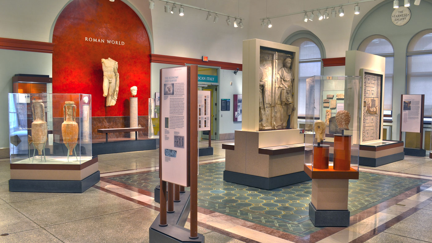
The Roman World
Roman civilization traced its roots back to nearly 1000 BC and lasted in one form or another until 500 AD. During this time it spread from the tiny settlement that became the city of Rome to master a world that reached to the edge of Central Asia and included much of Europe.
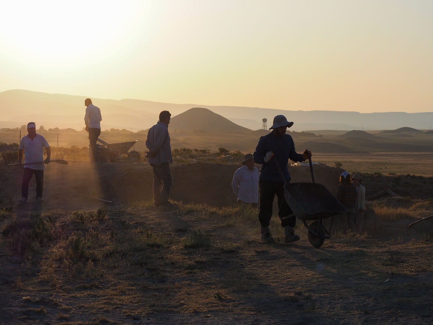
The Gordion Archaeological Project
Our goal is to make key Gordion information and interpretations more immediately accessible to the world at large, and to encourage the broadest interest in this historically important place and the many cultural associations that have marked it through the centuries.
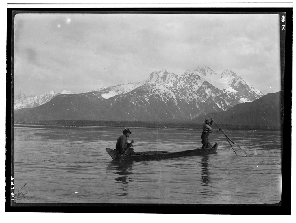
The Louis Shotridge Digital Archive
The Louis Shotridge Digital Archive makes available, for the first time, 4,000 high resolution digital images of Louis Shotridge’s objects, papers, photographs, and sound recordings.
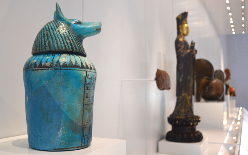
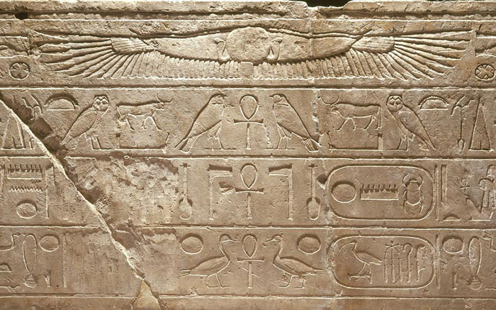
Write Your Name in Hieroglyphs
Translate Your Name into Hieroglyphs, the way an Egyptian scribe might have written it.
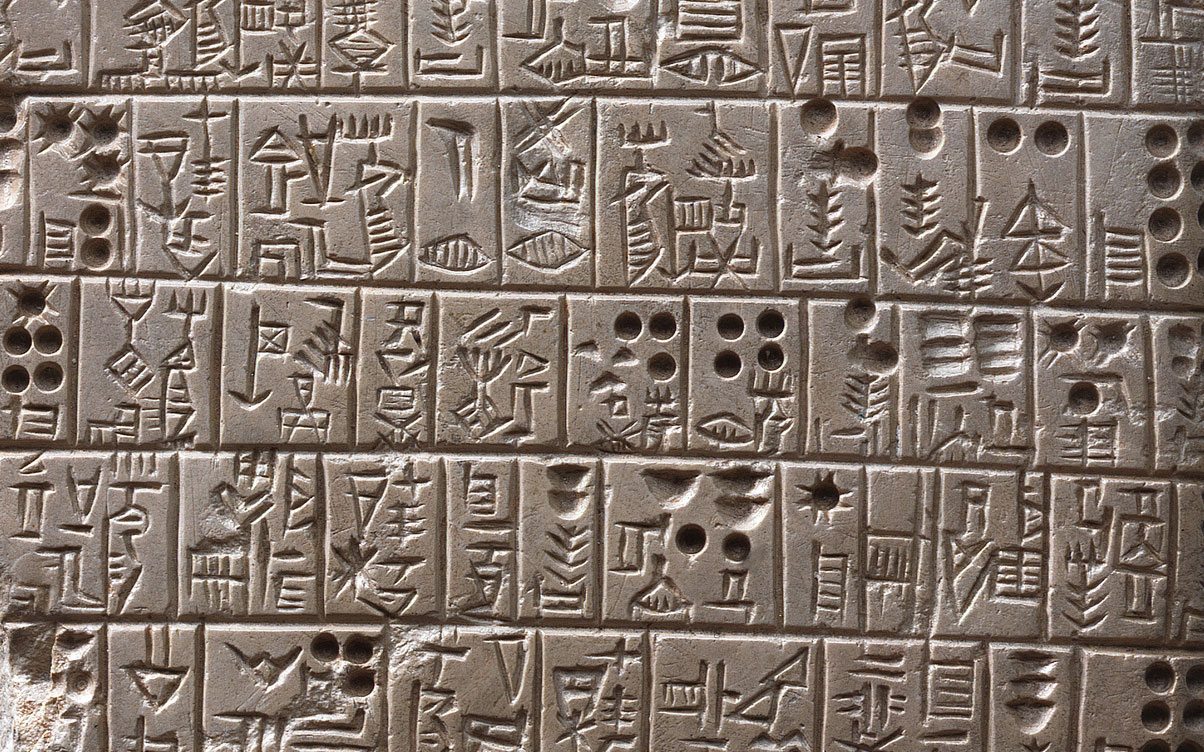
Write Your Name in Cuneiform
See your monogram in Cuneiform, the way an ancient Babylonian might have written it.